

Item NO.:
RK3566 PCBAOrder(MOQ):
20Product Origin:
ChinaColor:
blackShipping Port:
ShenzhenItem:
MOQ:
Sample:
Support:
RK3566 Chip Main Control Board is Used for Face Recognition Industrial Control Development Motherboard
Chapter One Product Overview
1.1. Overview
RK3566 Android all-in-one board adopts Rockchip's quad-core RK3566 chip solution with internal integrated NPU. RK3566 is a 64-bit CPU based on quad-core Cortex-A55 and adopts a brand new 22nm process; the main frequency is up to 1.8GHz; supports Google Android 11.0 operating system; GPU adopts MaliG522EE, which supports mainstream audio and video formats and picture decoding; RK3566 internally integrates AI neural network processor NPU, computing power up to 1TOPS, support a variety of AI development tools and interfaces.It is conducive to processing massive amounts of multimedia data such as video and images, and provides a strong foundation for machine deep learning; rich on-board interfaces and I/O, with rich and flexible connectivity and extensibility, support for commonly used external devices; rich interfaces, stable performance, can meet the requirements of different scenarios;
1.2. Characteristics
◆High performance: RK3566 is a 64-bit CPU based on quad-core A55 using a new 22nm process, with a frequency of up to 1.8GHz.,
It has super general-purpose computing performance, the GPU adopts Mali G522EE, and the CPU integrates AI neural network processing.
The NPU of the device has a computing performance of up to 1TOPS. It is conducive to processing massive amounts of multimedia data such as video and images, and it is deep for the machine.
Degree learning provides a strong foundation.
◆ High stability: RK3566 Android all-in-one board, in terms of hardware and software, adds its own unique technology to ensure the stability of the product, which can make the final product unattended for 7*24 hours.
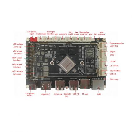
◆ High degree of integration: The RK3566 Android all-in-one board integrates gigabit Ethernet, WiFi, Bluetooth, 4Q/18W power amplifier, TF card expansion, IR remote control function, HDMI output, LVDS, eDP, MIPI screen, microphone, gravity sensing and other functions, which greatly simplifies the design of the whole machine.The ultra-thin motherboard design can make the whole machine design more beautiful.
◆Rich interface: support USB2.0/USB3.0 port, serial port, I2C interface, Weigen, GPIO, ADC, etc., can expand more peripheral equipment.It can meet common peripherals on the market, such as serial card swipe equipment, printing equipment, audio and video collection equipment, and so on.
◆ System customization: Support Android system optimization and customization, and provide system call interface API reference code.
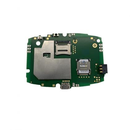
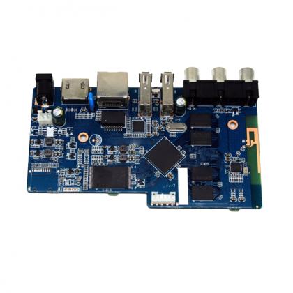
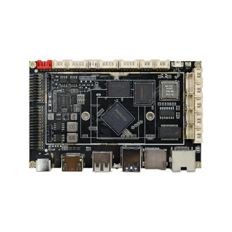
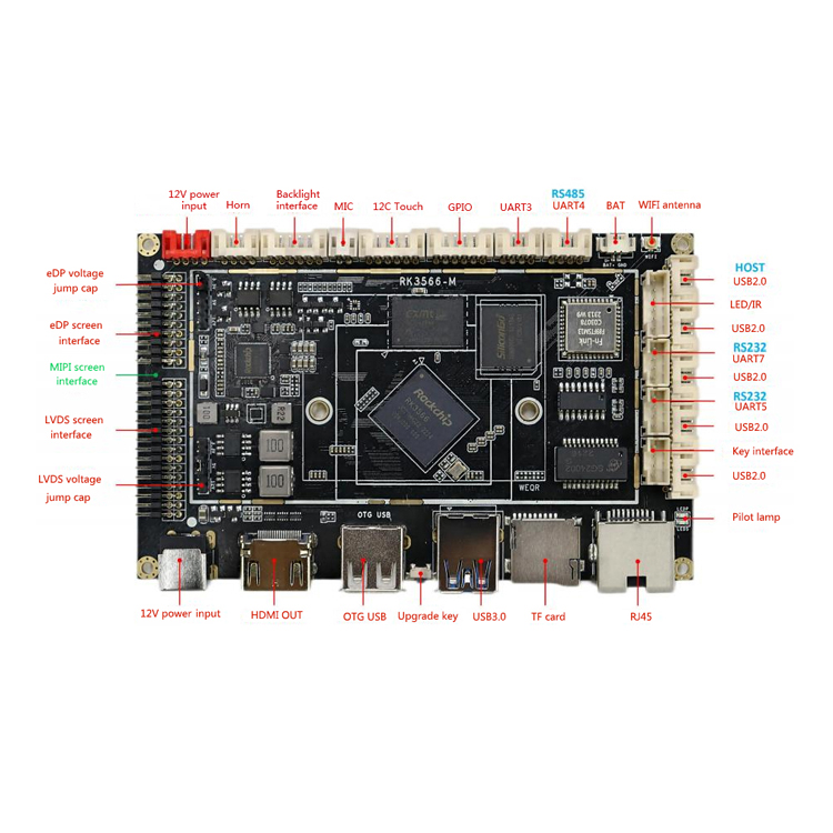
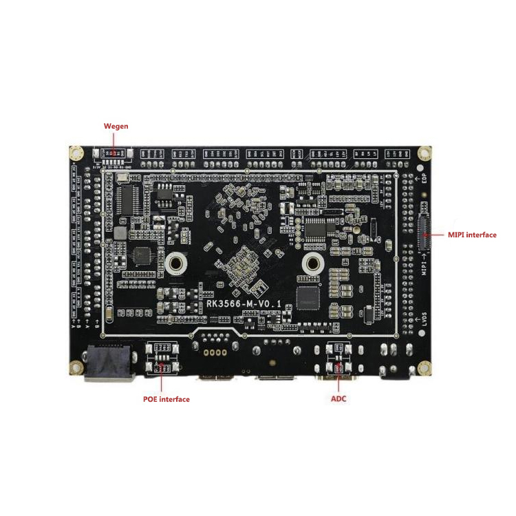
Chapter 2 Appearance and interface diagram
Chapter 3 Basic specifications, function list
3.1. Basic hardware specifications and functions
|
CPU |
Rockchip RK3566 (22nm process technology) |
|
|
Quad-core 64-bit Cortex-A55 processor with a maximum operating frequency of 1.8GHz |
|
GPU |
ARM G522EE graphics processor |
|
|
Support for OpenGL ES 1.1/2.0/3.2 , OpenCL2.0, Vulkan 1.1 |
|
NPU |
Embedded high-performance 2D acceleration hardware |
|
Codec |
Integrated RKNN NPU AI accelerator, 1Tops@INT8 performance |
|
memory Built-in storage capacity
|
Support one-click conversion of Caffe/TensorFlow/TFLite/ONNX/PyTorch/Keras/Darknet architecture model |
|
4K@60fps H.265/H.264/VP9 video decoding |
|
|
1080P@60fps H.265/H.264 video encoding |
|
|
network |
1GB/2GB/4GB/8GBLPDDR4/LPDDR4X (default 2GB) |
|
|
8GB/16GB/32GB/64GB/128GB eMMC built-in storage (default 16GB) supports TF card expansion |
|
|
Support RJ45 Gigabit network port, support POE module power supply |
|
Image rotation |
Support 2.4G WiFi, support Wi-Fi802.11b/g/n protocol |
|
|
Support Bluetooth function, V2.1+EDR/Bluetooth 3.0/3.0+HS/4.0 (optional) |
|
|
Support manual rotation of 0 degrees, 90 degrees, 180 degrees, 270 degrees; |
|
Display interface |
Support gravity sensor automatic screen rotation function (optional) |
|
Audio interface |
1*eDP interface (eDP1.3,4 lanes with 10.8Gbps), support 3.3V/5V/12V power supply 1*LVDS interface (single/dual, 6-bit/8-bit), support 7"-108" display, the highest support |
|
Hardware watchdog |
1080P60Hz output, support 3.3V/5V/12V power supply |
|
|
1*HDMI2.0, supports up to 4K60Hz output |
|
Touch screen interface |
1*MIPI screen interface, supports up to 1080P60Hz output |
|
RTC |
Support dual-screen simultaneous display |
|
USB |
1*Speaker output (2*18W4R THD<10%) |
|
Infrared reception |
1*Microphone input |
3.2. Basic software specifications and functions
|
Operating system |
Android 11 |
|
audio |
MP3, WMA, WAV, APE, FLAC, AAC, OGG, M4A, 3GPP and other formats |
|
video |
Support H. 265,H . 264,VP8,MAV,WMV,AVS,H . 1080P/2160P multi-video decoding of 263, MPEG4 and other video formats |
|
picture |
Support JPG, BMP, PNG and other image formats to browse and support rotation/slideshow playback/image enlargement function |
|
|
APK installer, email, calculator, browser, voice recorder, calendar, settings, clock, video player, search, address book, gallery, download, camera, music, resource manager |
|
The system comes with application software |
Multi-language |
|
Language support |
Standard Andriod keyboard, built-in Google pinyin input method |
|
Input method
System management
|
Optional third-party input method (Chinese, Korean, Japanese, etc.) |
|
Original ecological Android system, open root permissions, can be customized for product development |
|
|
Real-time remote monitoring, self-recovery from system crash, unattended for 7*24 hours |
|
|
Support OTA remote upgrade |
|
|
|
Support wifi display |
3.3. Working and storage environment
|
Operating ambient temperature |
-25℃~70℃, recommended -5℃~40℃ |
|
Working environment humidity |
10%~90%, no condensation |
|
Storage temperature |
-30℃~75℃, it is recommended to store at room temperature |
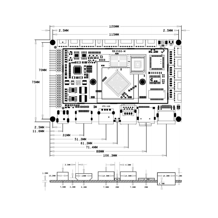
4.2. Specifications
Motherboard size: 120*75*12mm
Motherboard height: front ≤8mm, back ≤3mm
Number of PCB layers: 8 layers
PCB size: 120*75*1.6 mm
PCB color: black
PCB process: Sinking gold
Screw hole specification: φ2mm*4
Chapter 5 Interface Definition
5.1. Interface description
5.1.1, LVDS screen voltage jumper interface (6PIN/2.0)
|
Serial number |
definition |
attribute |
description |
|
1 |
12V |
Power supply |
12V output |
|
2 |
LVDS-VDD-IN |
Power supply |
LVDS voltage input |
|
3 |
5V |
Power supply |
5V output |
|
4 |
LVDS-VDD-IN |
Power supply |
LVDS voltage input |
|
5 |
3.3V |
Power supply |
3.3V output |
|
6 |
LVDS-VDD-IN |
Power supply |
LVDS voltage input |
5.1.2 LVDS interface (2x15PIN/2.0)
|
Serial number |
definition |
attribute |
description |
|
1 |
POWER |
Power supply |
Screen power output 3.3V/5V/12V specific voltage is selected by the jumper
|
|
2 |
POWER |
Power supply |
|
|
3 |
POWER |
Power supply |
|
|
4 |
GND |
ground |
ground |
|
5 |
GND |
ground |
ground |
|
6 |
GND |
ground |
ground |
|
7 |
LVDS-A-DON |
output |
Negative data output |
|
8 |
LVDS-A-DOP |
output |
Positive data output |
|
9 |
LVDS-A-DIN |
output |
Negative data output |
|
10 |
LVDS-A-DIP |
output |
Positive data output |
|
11 |
LVDS-A-D2N |
output |
Negative data output |
|
12 |
LVDS-A-D2P |
output |
Positive data output |
|
13 |
GND |
ground |
ground |
|
14 |
GND |
ground |
ground |
|
15 |
LVDS-A-CLKN |
output |
Negative data output |
|
16 |
LVDS-A-CLKP |
output |
Positive data output |
|
17 |
LVDS-A-D3N |
output |
Negative data output |
|
18 |
LVDS-A-D3P |
output |
Positive data output |
|
19 |
LVDS-B-DON |
output |
Negative data output |
|
20 |
LVDS-B-DOP |
output |
Positive data output |
|
21 |
LVDS-B-DIN |
output |
Negative data output |
|
22 |
LVDS-B-D1P |
output |
Positive data output |
|
23 |
LVDS-B-D2N |
output |
Negative data output |
|
24 |
LVDS-B-D2P |
output |
Positive data output |
|
25 |
GND |
ground |
ground |
|
26 |
GND |
ground |
ground |
5.1.1.3, MIPI screen interface (31PIN/0.3)
|
Serial number |
definition |
attribute |
description |
|
1 |
LED+ |
Backlight power supply |
Backlight positive electrode |
|
2 |
LED+ |
Backlight power supply |
Backlight positive electrode |
|
3 |
LED+ |
Backlight power supply |
Backlight positive electrode |
|
4 |
GND |
ground |
ground |
|
5 |
LED- |
Backlit ground |
Backlight negative electrode |
|
6 |
LED- |
Backlit ground |
Backlight negative electrode |
|
7 |
LED- |
Backlit ground |
Backlight negative electrode |
|
8 |
LED- |
Backlit ground |
Backlight negative electrode |
|
9 |
GND |
ground |
ground |
|
10 |
GND |
ground |
ground |
|
11 |
MiPi-D2P |
output |
Positive data output |
|
12 |
MiPi-D2N |
output |
Negative data output |
|
13 |
GND |
ground |
ground |
|
14 |
MiPi-DIP |
output |
Positive data output |
|
15 |
MiPi-DIN |
output |
Negative data output |
|
16 |
GND |
ground |
ground |
|
17 |
MiPi-CLKP |
output |
Positive data output |
|
18 |
MiPi-CLKN |
output |
Negative data output |
|
19 |
GND |
ground |
ground |
|
20 |
MiPi-DOP |
output |
Positive data output |
|
21 |
MiPi-DON |
output |
Negative data output |
|
22 |
GND |
ground |
ground |
|
23 |
MiPi-D3P |
output |
Positive data output |
|
24 |
MiPi-D3N |
output |
Negative data output |
|
25 |
GND |
ground |
ground |
|
26 |
NC |
NC |
NC |
|
27 |
RESET |
output |
reset |
|
28 |
NC |
NC |
NC |
|
29 |
VDDIO1.8V |
output |
VDD1.8V |
|
30 |
VDD3.3V |
output |
VDD3.3V |
|
31 |
VDD3.3V |
output |
VDD3.3V |
5.1.4, eDP screen interface (2x10PIN/2.0)
|
Serial number |
definition |
attribute |
description |
|
1 |
VCC |
Power supply |
Screen power output 3.3V/5V/12V specific voltage is selected by the jumper
|
|
2 |
VCC |
Power supply |
|
|
3 |
GND |
ground |
ground |
|
GND |
ground |
ground |
|
|
5 |
EDP-DON |
output |
Negative data output |
|
6 |
EDP-DOP |
output |
Positive data output |
|
7 |
EDP-D1N |
output |
Negative data output |
|
8 |
EDP-D1P |
output |
Positive data output |
|
9 |
EDP-D2N |
output |
Negative data output |
|
10 |
EDP-D2P |
output |
Positive data output |
|
11 |
EDP-D3N |
output |
Negative data output |
|
12 |
EDP-D3P |
output |
Positive data output |
|
13 |
GND |
ground |
ground |
|
14 |
GND |
ground |
ground |
|
15 |
EDP-AUXN |
output |
Negative data output |
|
16 |
EDP-AUXP |
output |
Positive data output |
|
17 |
GND |
ground |
ground |
|
18 |
GND |
ground |
ground |
|
19 |
3V3 |
output |
3.3V power output |
|
20 |
HPD |
input |
HPD detection foot |
5.1.5, eDP screen voltage jump cap interface (6PIN/2.0)
|
Serial number |
definition |
attribute |
description |
|
1 |
12V |
Power supply |
12V output |
|
2 |
EDP-VDD-IN |
Power supply |
EDP voltage input |
|
3 |
5V |
Power supply |
5V output |
|
4 |
EDP-VDD-IN |
Power supply |
EDP voltage input |
|
5 |
3.3V |
Power supply |
3.3V output |
|
6 |
EDP-VDD-IN |
Power supply |
EDP voltage input |
5.1.6, power interface (4PIN/2.0)
|
Serial number |
definition |
attribute |
description |
|
1 |
GND |
ground |
ground |
|
2 |
GND |
ground |
ground |
|
3 |
12V IN |
Power supply |
12V power supply |
|
4 |
12V IN |
Power supply |
12V power supply |
5.1.7, speaker output interface (4PIN/2.0)
|
Serial number |
definition |
attribute |
description |
|
1 |
LP |
output |
Positive left channel output |
|
2 |
LN |
output |
Left channel output negative |
|
3 |
RN |
output |
Negative output of the right channel |
|
4 |
RP |
output |
Positive output of the right channel |
5.1.8, screen backlight interface (6PIN/2.0)
|
Serial number |
definition |
attribute |
description |
|
1 |
12V |
Power supply |
12V output |
|
2 |
12V |
Power supply |
12V output |
|
3 |
BL |
output |
Backlight enabled (5V) |
|
4 |
ADJ |
output |
Backlight brightness adjustment (0~5V) |
|
5 |
GND |
ground |
ground |
|
6 |
GND |
ground |
ground |
5.1.9, microphone interface (2PIN/2.0)
|
Serial number |
definition |
attribute |
description |
|
1 |
MICP |
input |
MIC positive input |
|
2 |
MICN |
input |
MIC negative input |
5.1.10, touch screen interface (6PIN/2.0)
|
Serial number |
definition |
attribute |
description |
|
1 |
3.3V |
Power supply |
3.3V output |
|
2 |
INT |
Input/output |
Interrupt data |
|
3 |
RST |
Input/output |
Reset data |
|
4 |
SCL |
Input/output |
IC clock |
|
5 |
SDA |
Input/output |
IC data |
|
6 |
GND |
ground |
ground |
5.1.11, GPIO interface (6PIN/2.0)
|
Serial number |
definition |
attribute |
description |
|
1 |
3/5V |
Power supply |
5V/3.3V (default) output |
|
2 |
IO1 |
Input/output |
Default high level |
|
3 |
IO2 |
Input/output |
Default high level |
|
4 |
IO3 |
Input/output |
Default low level |
|
5 |
IO4 |
Input/output |
Default low level |
|
6 |
GND |
ground |
ground |
5.1.12. UART Serial Port (4PIN/2.0)
|
Serial number |
definition |
attribute |
description |
|
1 |
3/5V |
Power supply |
5V/3.3V (default) output |
|
2 |
TX3 |
output |
send |
|
3 |
RX3 |
input |
receive |
|
4 |
GND |
ground |
ground |
5.1.13 UART Serial port (RS485) port (4PIN/2.0)
|
Serial number |
definition |
attribute |
description |
|
1 |
3/5V |
Power supply |
5V/3.3V (default) output |
|
2 |
TX4A |
output |
Send/485-A (default) |
|
3 |
RX4B |
input |
Receive/485-B (default) |
|
4 |
GND |
ground |
ground |
5.1.14, BAT Battery port (2PIN/1.25)
|
Serial number |
definition |
attribute |
description |
|
1 |
BAT+ |
input |
3V input |
|
2 |
GND |
ground |
ground |
5.1.15, Remote control and indicator port (6PIN/2.0)
|
Serial number |
definition |
attribute |
description |
|
1 |
3.3V |
Power supply |
3.3V output |
|
2 |
IR |
input |
Infrared signal input |
|
3 |
GND |
ground |
ground |
|
4 |
P |
output |
Power indicator (red) light positive |
|
5 |
S |
output |
System indicator (green) light positive |
|
6 |
GND |
ground |
ground |
5.1.16, UART serial port (RS232) interface (4PIN/2.0)
|
Serial number |
definition |
attribute |
description |
|
1 |
5/3V |
Power supply |
5V (default)/3.3V output |
|
2 |
TX7 |
output |
send |
|
3 |
RX7 |
input |
receive |
|
4 |
GND |
ground |
ground |
5.1.17, UART serial port (RS232) interface (4PIN/2.0)
|
Serial number |
definition |
attribute |
description |
|
1 |
5/3V |
Power supply |
5V (default)/3.3V output |
|
2 |
TX5 |
output |
send |
|
3 |
RX5 |
input |
receive |
|
4 |
GND |
ground |
ground |
5.1.18, button interface (4PIN/2.0)
|
Serial number |
definition |
attribute |
description |
|
1 |
K |
input |
Upgrade button/volume+ |
|
2 |
R |
input |
Reset button |
|
3 |
P |
input |
Switch button |
|
4 |
GND |
ground |
ground |
5.1.19, USB-HOST interface (4PIN/2.0)
|
Serial number |
definition |
attribute |
description |
|
1 |
5V |
Power supply |
5V output |
|
2 |
DM |
Input/output |
Data negative |
|
3 |
DP |
Input/output |
Positive data |
|
4 |
GND |
ground |
ground |
5.1.20, USB-HOST interface (4PIN/2.0)
|
Serial number |
definition |
attribute |
description |
|
1 |
5V |
Power supply |
5V output |
|
2 |
DM |
Input/output |
Data negative |
|
3 |
DP |
Input/output |
Positive data |
|
4 |
GND |
ground |
ground |
5.1.21, USB-HOST interface (4PIN/2.0)
|
Serial number |
definition |
attribute |
description |
|
1 |
5V |
Power supply |
5V output |
|
2 |
DM |
Input/output |
Data negative |
|
3 |
DP |
Input/output |
Positive data |
|
4 |
GND |
ground |
ground |
5.1.22, USB-HOST interface (4PIN/2.0)
|
Serial number |
definition |
attribute |
description |
|
1 |
5V |
Power supply |
5V output |
|
2 |
DM |
Input/output |
Data negative |
|
3 |
DP |
Input/output |
Positive data |
|
4 |
GND |
ground |
ground |
5.1.23, USB-HOST interface (4PIN/2.0)
|
Serial number |
definition |
attribute |
description |
|
1 |
5V |
Power supply |
5V output |
|
2 |
DM |
Input/output |
Data negative |
|
3 |
DP |
Input/output |
Positive data |
|
4 |
GND |
ground |
ground |
5.1.24, Wiegand interface (6PIN/1.25)
|
Serial number |
definition |
attribute |
description |
|
1 |
5/3V |
Power supply |
5V (default)/3.3V output |
|
2 |
S0 |
output |
Send data 0 |
|
3 |
S1 |
output |
Send data 1 |
|
4 |
R0 |
input |
Receive data 0 |
|
5 |
R1 |
input |
Receive data 1 |
|
6 |
GND |
ground |
ground |
5.1.25 ADC Conversion interface (2PIN/1.25)
|
Serial number |
definition |
attribute |
description |
|
1 |
AD1 |
input |
ADC input (18V) |
|
2 |
GND |
ground |
ground |
5.1.26 POE power supply interface (4PIN/1.25)
|
Serial number |
definition |
attribute |
Description |
|
1 |
VA1 |
output |
RJ45 PIN1& PIN2 taps |
|
2 |
VA2 |
output |
RJ45 PIN1& PIN2 taps |
|
3 |
VB1 |
output |
RJ45 PIN1& PIN2 taps |
|
4 |
VB2 |
output |
RJ45 PIN3 &PIN6 taps |
5.2. Other standard interfaces and functions
|
name |
Seat specifications |
description |
|
DC 12V power interface |
DC-5.5*2.1mm female head |
12V power input |
|
HDMI interface |
Standard HDMI female |
Maximum support 4K output |
|
USB interface |
Standard USB interface |
HOST/OTG mode USB |
|
Upgrade button |
Non-self-locking button |
UBOOT button |
|
USB3.0 interface |
Standard USB3.0 interface |
HOST mode USB |
|
TF card holder |
Standard TF card holder |
Support up to 128GB |
|
Ethernet interface |
RJ45 interface |
10/100M/1000M |
|
WIFI antenna holder |
IPEX-1 generation male |
Adaptive Ethernet |
Chapter VI Precautions
▲ When touching the motherboard, please wear electrostatic protection tools such as electrostatic bracelets (to be well grounded);
▲ Do not live assembly, wiring and other operations;
▲ Please check the motherboard interface definition and peripheral interface definition, there can be no connection error, connection reverse;
▲ Please use M2 flat round head screws to fix the motherboard, do not use countersunk, larger screws; When twisting the screw, pay attention to avoid the motherboard deformation and bending;
▲ Pay attention to level matching of IO port, serial port and enable pin;
▲ Pay attention to the power of the external screen, please consider external power supply if the power is larger;
▲ Pay attention to the overall power of the product, choose a power supply with enough power;


 English